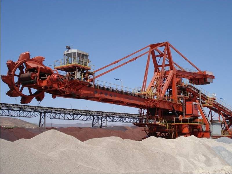
The bucket wheel stacker and reclaimer is consisted of upper steel structure, long traveling system, slewing system, luffing mechanism, bucket mechanism, boom conveyor, portal support frame, slewing platform, triple conveyor, lubrication system, water spray dust suppression system, accessory structure, operation room, , transformor room, electrical control system, monitoring and alarm system, power supply, ventilation, illumination etc.
Stacker and relcaimer is equipped with various safty devices, such as location indenfing device, material height detection system, slewing and luffing monitoring system, anti-collision and limited switches.
Stacking operation can be setted as per the changing of reposal angle of material pile and fixed point stacking control data. Reclaiming operation is limited within the width of pile, the slewing angle of boom must be controled to avoide buckets touches the ground belt conveyor and foundation of equipment.
The working wind speed of stacker and reclaimer is 20m/s, the wind speed detector and rail clamp is interlocked and connected to operation room, when wind speed exceed 20m/s, automatic wind speed detector will give pre-alarm. The max. Wind speed that rail clamp can bear is 35m/s, while the max. for anchor device is 55m/s. stacker and reclaimer is able to travel to anchor location with wind speed 25m/s and fixted the equipment in anchor location

Description of Various Parts
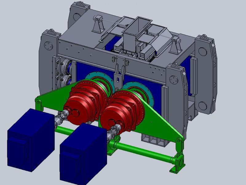
1. Long traveling system
1.1. The design of traveling drive unit considered terrible maintenance situation of rail, and moving requirements when the boom is located at worst position at max. wind speed.
The rail model is 90IB/YaRa as per requirement.
1.2. The design of traveling system can ensure the synchronization of bogie, motor load acted on and along with rail evenly, which will enable equipment moving stablely.
1.3. The VVV drive unit is combined with motor, brake and gearbox. The bearing of traveling wheel used double labyrinth mechanism and bone frame lip seal, which will ensures iron powder will not come into bearing.
1.4. Starter of traveling drive unit will ensure stable speed acceleration and reduction, and avoid rail sway on horizontal direction.

Traveling System
1.5. To avoid equipment moving in storm, rail clamp, rail cleaner, two grades limited switches, buffer stopper, anchor device are designed for the machine, and at certain location, there is location encoder, this will help machine to adjust the position, the space distance is 50m. Traveling drvie unit is interlocked with rail clamp and anchor device, rail clamp is able to release automatically before traveling operation.
1.6. The wheel pressure under the same portal support leg should be approx. the same, to ensure the convenience of maintenance and repairing; jack up plated is designed for very support leg, and clearly marked with functional sign. Connection of balance beam and pivot is of pin kind, which will increase stability running of machine. There are two edges of wheel, and the wheel and rail can touches sufficiently, the material of wheel is 350 CrMnSi, after heat treatment the surface hardness of wheel will reach HB363-401, in depth of 10mm, the hardness is bigger than HB269.

Portal Support Frame
2.Bucket wheel system
The bucket is celless design with sufficient rigidity, bucket teeth is made of meganetic iron material, bucket system is easier for line plates, buckets and teeth changing. The drive unit of bucket system is of hydraulic kind which is made by HAGGLUNDS.
The angle of chute and horizontal plan is 60°, the smallest location is 55°, more than 20mm thickness anti-wearing liner plates are designed for the chute, all the liner plates are bolted to the chute which is easier for changing. The service life of line plate is 2 times than 16 Mn materials which are normally used on moment market. Every plate is marked with code number, which is easier for purchasing and replacement.
Adjusting space of bucket arc buffer plate and bucket shirt plate is 2-7mm; buckets are machined on 8m numerical machine tool as complete one piece, which will ensure dimension of shaft hole, concentricity and roundness of out circle. Bucket blade is made of special anti-wearing steel, has high strength and tenacity.

Bucket Wheel Mechanism
3. Tripper Conveyor
Stacker and reclaimer used fixed single tripper with sufficient rigidity, when machine startup and stop, there is no impact force, the whole machine is able to moving stablely.
The belt width is 1600 mm; belt speed is 2.8 m/s, max. capacity is 1980 tph, tough angle of tough angle is 35, carring side designed traning idlers, the space distance of training idler is less than 15m, the diameter of idler is 133mm, the average service life of idler should be more than 50000hours, rifiction factor not exceed 0.02, the space distance of carrying idler is not bigger than 1000mm, while return idler not bigger than 2400mm.
There are two grades of high efficiency heavy duty scraper cleaner at every point of discharge pulley. All pulleys are of forged and welding structure, tested with static and active balance test, which can be selected as per belt and belt tension force requirements.
Maximum angle of belt conveyor and ground plan is 16, design of tripper should decrease the elevation of discharge pulley at most extent to extend traveling distance of stacker and reclaimer.
Cross ladder is designed at lower location of tripper, the net width of walkway that at two sides of tripper conveyor is 800mm. Design of tripper sufficiently considered sudden load that caused by brake and startup. Following safety devices are designed on tripper conveyor.
- Belt sway switch.
- Speed signal switch
- Double direction pullying cord switch (two sides of belt conveyor)
- Belt split protection switch.
- Material block switch.

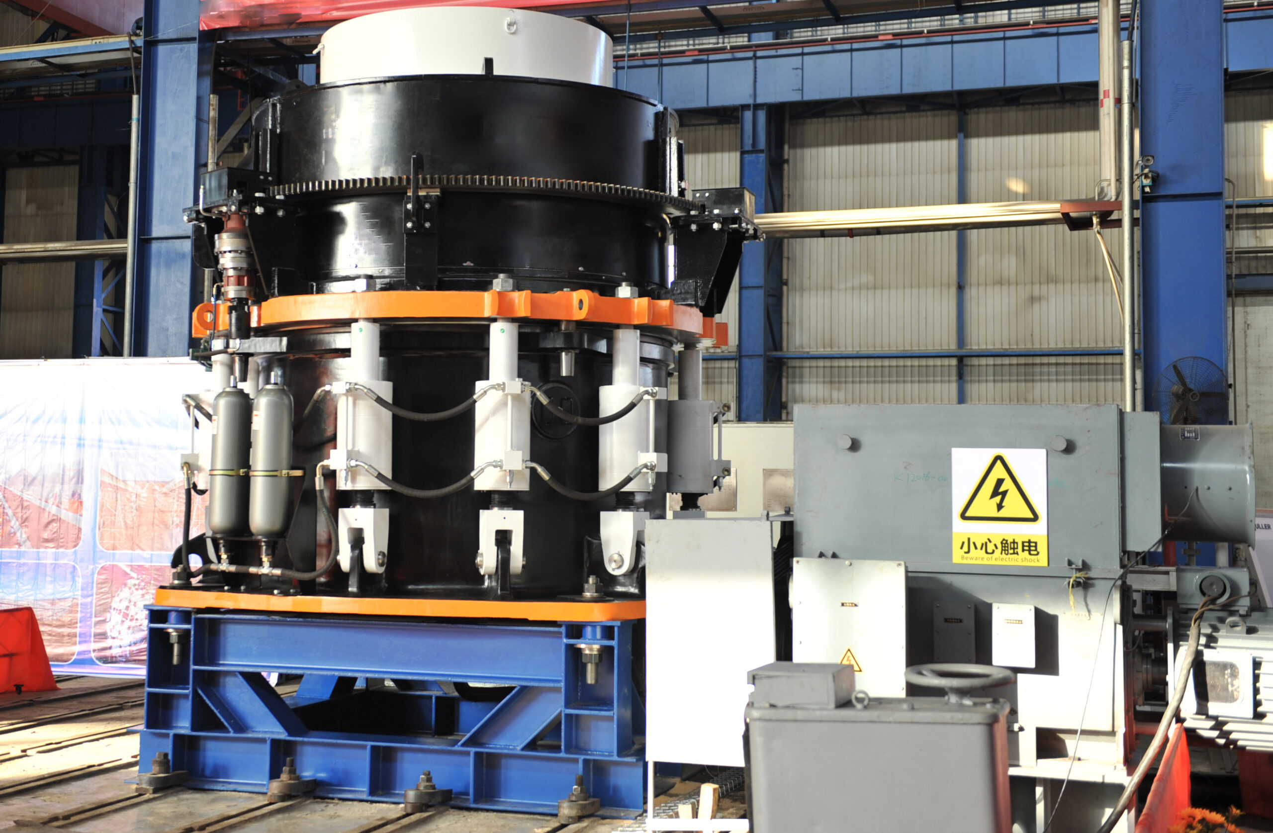
4. Boom Luffing Mechanism
Boom luffing operation is drived by hydraulic system, there are two hydraulic cylinder working at the same time in same phrase, hydraulic system have oil supply pump, filters, balance valve, lock device etc. This will ensure the luffing operation is stable, no vibration and sudden rush.
There is auto lock device of return oil pipeline of hydraulic system, this will prevent sudden falling down of boom, and also ensure the balance of whole equipment when the boom laid on material pile or ground. When one hydraulic cylinder is broken, the other one is still able to hold the moment location of boom frame. Even when hydraulic pipe line is broken, the boom can hold the position, will not falling down.
During non-operation period, the cylinder size does not have any elastic changing. Full set seal of hydraulic parts are reliable, there is no oil leaking for whole hydraulic system.
Maximum luffing angle of boom frame to horizontal is not bigger than 12, setting of luffing limited switch is related to angle measurement, the instant luffing angle will be measured and sent to operation room, displayed the value on the touching screen.

5. Boom Conveyor
The boom conveyor is designed for two direction running, is able to startup when it is fully loaded, the belt sway margin will not exceed 5% for full width of conveyor.
The belt width is 1600mm, max. Capacity is 1980TPH, reated capacity is 1800 TPH.

The walkway with that around the drive station is 1000mm, for the rest location the width is 0.8mm. To avoide over take-up force that acted at the edge of belt, we designed transit idlers at both tail and head location of boom conveyor.
Fixed hydraulic take-up is designed for belt conveyor take-up, which can be adjusted conveniently; material flow will not be afftected during take-up operation. Drive unit is mechanical outside driving, equipped with reliable brake device.

6. Upper Steel Structure
The upper steel structure is welded within workshop, connected by high strength bolt or welded together on site, the connecting of beam will not below AISC standard.
The connecting of main structure, such as truss, equipment support, platform used high strength bolts or welding, the accessory structure of belt conveyor, such as walkways, ladders and handrails use normal standard bolt for connection.
For frequent operation, checking and maintenance place, we designed permanent maintenance platform, the bearing load of the platform is more than 4000N/M2, n, floor plates of ladder, and platform is made of galvanized gratings with sufficient strength. The smallest width of walkway and ladder should be 800mm; platform around drive unit, width should bigger than 1000mm.
Each platform should equipment with a accessing ladder which is made of steel, the angle of ladder and ground should bigger than 60°, all the ladders designed with handrails, the handrail of ladder, walkway, is made of standard pipe with diameter of 30mm. the biggest space distance of pole is 1000mm, the height of handrail is 1150mm, horizontal bar is installed at the height of 600mm from the platform floor. The mimimun radius of handrail bending position should be 50mm; the biggest radius should be 100mm.
All the structure will be sandblasted and remove rust before welding,key components will preassembled in and disconnected for transportation, connected with high strength bolts on site.
After rust removing, sand blasting the surface of structure before painting, reaches grade Sa 2.5, the final dry coat thickness must reach 280μm. Paints is suitable for terrible condition at seaside, the painting life guarantee is 5 years.

7. Operation Cabinet
Operation cabinet is located at the front end of boom conveyor. Operator of stacker and reclaimer can clearly see the bucket wheel working condition. The cabinet is isulated, dust proof, water proof, fir resistant, heat insulated, equipped with AC and sufficient lighting.
We also designed auto leveling device for the cabinet, which consisted by two hydraulic cylinders that below the room, no matter when the boom is luffing up or down, the operation room is always at horizontal position.

8. Center hopper, Chute and Hanging Buffer Device
There is sufficient space at material transfer point to avoid material block when power suddenly shut off. The material chute at the head of boom conveyor is flexible, which will move up under stacking mode.
Material receiving point on belt conveyor designed buffer device which will release impact force. We designed good sealing for belt conveyor, and make the material flow falling to the center of belt to avoid material split out or creat side force acted to the side of belt.
The minimum plate thickness of chute is 7mm, wearing surface is bolted by 20mm thickness anti-wearing plates. The ends of chute designed rubber curtain.
All discharging chute, hopper is made of plate with minimum thickness of 8mm, the welding requirements as per AWS D1.1. The inclined angle of hopper and ground should be minimum 60 degrees.
On material discharge chute pipe, there is maintenance door and watching eyes, the maintenance door size is 600mX 600m, the dimension of watching eyes is 300mmX 300mm. The function switching is through electrical three way flap gate and direct chute.

9. Dust Suppression System
Bucket wheel stacker and reclaimer provided one complete set of water spray dust suppression system at every material transfer point, the system can be centralized controlled in operation room. The water tank volumn is bigger than 10m3; water spray points are as below:
- Head of boom conveyor (working when stacking)
- Chute of bucket (working when reclaiming)
- Middle discharge chute (working when reclaiming)
- Lower discharge chute (working when reclaiming)
Dust density at material transfer point and noise level within operation room reaches related standard requirement.
10. Saftey Device
10.1 Safty protection device for long traveling system
- Wind speed alarm and protection
- Interlock of rail clamp, anchor device and traveling system.
- Limited switch located at traveling ends of rail.
- Lingt and sound alarm when equipment is running
10.2 Safty protection device for slewing mechanism
- Limited switches of slewing angle.
- Moment limited slewing coupling.
- Interlock among anchor device, luffing, slewing, traveling mechanism.
- Slewing angle will be displayed on screen.
10.3 Luffing mechanism protection.
- Limited switch of luffing
- Luffing angle display.
When boom frame cross ground belt conveyor, slewing mechanism is interlocked with luffing height, during normal operation the interlock will be released.
10.4 Protection of bucket mechanism
Torque moment limited device.
10.5 Boom conveyor protection device, boom conveyor and ground belt conveyor is interlocked in programe,to avoid material block.
10.6 Protection devices for tripper conveyor.
10.7 Operation limit switch of rail clamp motor.
10.8 Other protection devices, such as boom anti-collision device. Thunderstrikeprotection device.
10.9 All transformers have shortcut, overload, and overheat protection.
10.10. All motors have overload, shortcut and break off protection.
10.11. Total power switch have power leaking and display devices.
10.12. Stacker and reclaimer designed complete, safe earthing system.
11. Structure Stress Analyse
Our design department use softwear of inventor, solidworks, built active three-dimensional model to analysis the strees of structure of stacker and reclaimer. Which will makes the structure of equipment more reasonable, stable and so extent service life of machine.
Shifting stress analyse of upper steel structure

The indication drawing is when upper structure at horizontal position, the deforming points is enlarged 50 times.

Stress of slewing platform

Under operation status, the stress at each postion of structure refers to drawing below: